The accurate measurement and stable operation of a quantitative feeder are highly dependent on strict installation specifications. Following scientific and meticulous installation standards not only ensures that the equipment meets performance requirements upon commissioning, but also significantly reduces the difficulty of subsequent operation and maintenance and the failure rate, achieving true “compliance in installation, ease in operation and maintenance.”
Compliance in installation is the core prerequisite for ensuring the performance of a quantitative feeder, covering specifications in environmental, mechanical, electrical, and safety aspects.
- Environmental Selection and Foundation Requirements
● Avoid Vibration Sources: The installation location must be away from strong vibration equipment such as crushers, ball mills, and vibrating feeders, or effective vibration isolation measures must be taken to minimize the impact of vibration on load cells, speed sensors, and material conveying status, ensuring measurement accuracy.
● Prefer Indoor Environment: Install indoors if possible. If outdoor installation is unavoidable, a protective cover must be provided, and its design must not hinder equipment operation, belt conveying, or measurement functions.
● Solid and Level Foundation: The scale body must be installed horizontally on a solid, non-vibrating platform. The foundation must be capable of bearing the equipment weight and operational loads to prevent settlement or deformation.
- Core Mechanical Installation Specifications
● Precise Alignment and Leveling
‣ Horizontally lift the scale body onto the foundation using lifting eye bolts, ensuring that the longitudinal centerline of the belt strictly aligns with the outlet centerline of the feed hopper and the centerline of the discharge chute, to prevent material off-center loading that could cause belt misalignment and measurement errors.
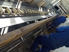
‣ Use a straightedge and spirit level (both no less than 1000mm in length) to carefully check the levelness in both transverse and longitudinal directions on the belt surface. The allowable tilt is typically ≤2mm per full length.
‣ Level the equipment using thin steel shims at the anchor bolt positions. After adjustment, secure with beveled washers, spring washers, and locknuts. The levelness must be rechecked after installation.
● Belt Tension and Tracking Adjustment
‣ Check the factory-set belt tension, confirming that the upper edge of the automatic tensioning mechanism’s scale aligns with the horizontal diagonal lines of the square holes on both sides of the frame. If misaligned, adjust the tensioning nut until aligned. Ensure the tensioning device functions properly to maintain constant belt tension, which is crucial for stable tare weight and measurement accuracy.
‣ Install anti-tracking deviation devices (self-aligning idlers or mechanisms) and ensure they are effective. Install a belt misalignment switch for alarm if necessary.
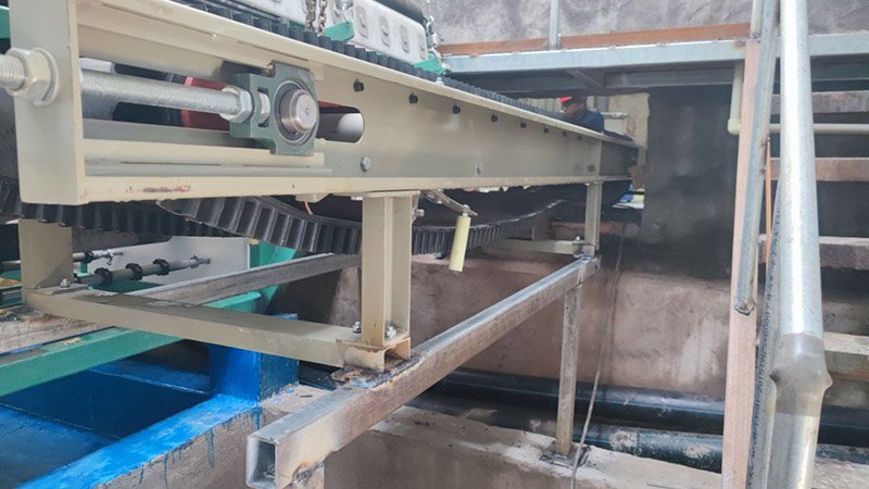
● Installation of Key Components
‣ Activation of Weighing System: Carefully clean the contact surfaces between the load-bearing screw tip and the steel ball. Screw down the load-bearing screw until it makes good contact with the steel ball, then tighten the locking nut. Loosen and lift the protective support screw of the weighing frame so that the weight of the frame is fully transferred through the load-bearing screw and steel ball to the load cell. Check the gap of the overload protection screw below the sensor (typically factory-set to 1–1.5mm).
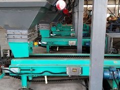
‣ Hopper and Discharge Hood: Install according to design requirements. The hopper should be positioned directly above the tail end of the belt, with the vertical distance between the hopper outlet and the belt controlled to approximately 40mm. Ensure the horizontal and vertical gates operate smoothly, used for normal feeding, adjusting material layer thickness, and isolating material during maintenance.
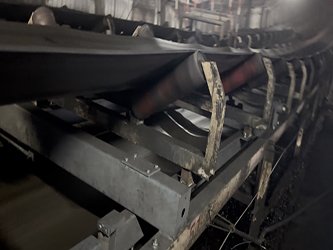
‣ Idlers and Rollers: Ensure all idlers (especially the weighing idlers), drive roller, and tail roller are aligned, parallel, level, and rotate freely. The weighing idlers must ensure coaxiality, bearing flexibility, and lateral levelness, with their height precisely adjusted according to the scale model. Allow sufficient distance (at least one idler spacing) after the feed point so that the material stabilizes before entering the weighing section.
‣ Spill Prevention Device: Install a chute liner or baffle plate at the lower part of the hopper if necessary, depending on material flowability, to prevent material spillage during operation.
- Electrical and Instrumentation Installation Specifications
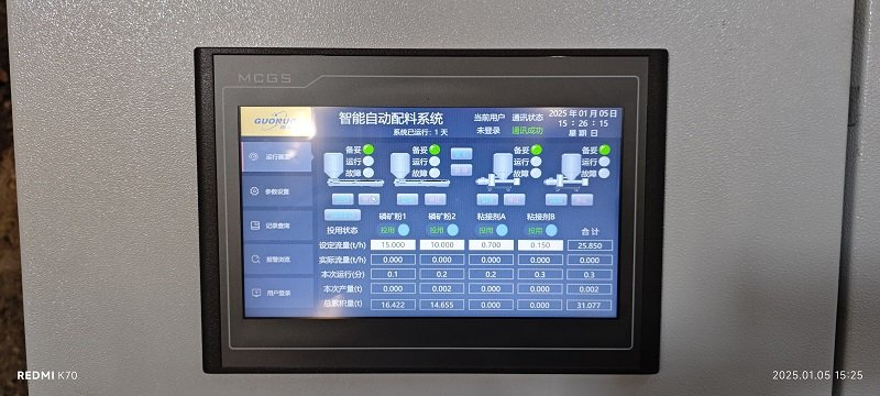
● Field wiring and installation of instruments (e.g., weight controller, speed sensor) must be performed by qualified electrical personnel according to contract and technical drawings, ensuring standardized wiring, reliable connections, and proper shielding.
● The instrument installation location should be convenient for observation and operation. The scale body’s anchor points must be well grounded.
- Safety Regulations Throughout
● Shutdown Work: Equipment must be shut down before installation and commissioning, and protective devices (e.g., locking gate, energy isolation) must be used to prevent accidental startup or material flow.
● Commissioning Safety: Use a non-hazardous substitute material with similar properties to the raw material during commissioning. Ideally, disconnect the feeder outlet from downstream equipment and collect test material in a container. Confirm that all motors rotate in the correct direction.
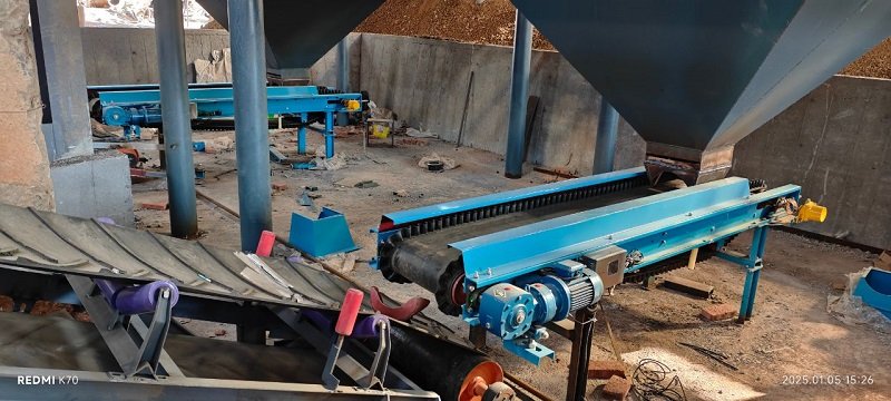
● Space Clearance: When multiple units operate in parallel, leave at least 1 meter of clearance between equipment and between equipment and walls for operation and maintenance access.
The “compliance in installation” for a quantitative feeder is far more than simply placing the equipment in position—it is a scientific and rigorous process encompassing environmental assessment, precision adjustment, safety protection, and system integration. The rigor and attention to detail invested during installation represent the best investment for achieving long-term “ease in operation and maintenance” and efficient, stable operation.